Mathematical Modeling of a Single Leg Robot
#Robotics #Modeling
General Overview of the Problem
The problem can be simply stated as this: We have a mass $M$ attached to a leg. The leg has a hip and a knee. A torque can be applied to each of these joints, named $\tau_h$ and $\tau_k$. The height of the mass $M$ is called $y$. There is also a force acting on the point where the leg touches the ground. This force is called $F$. These are shown in the image below:
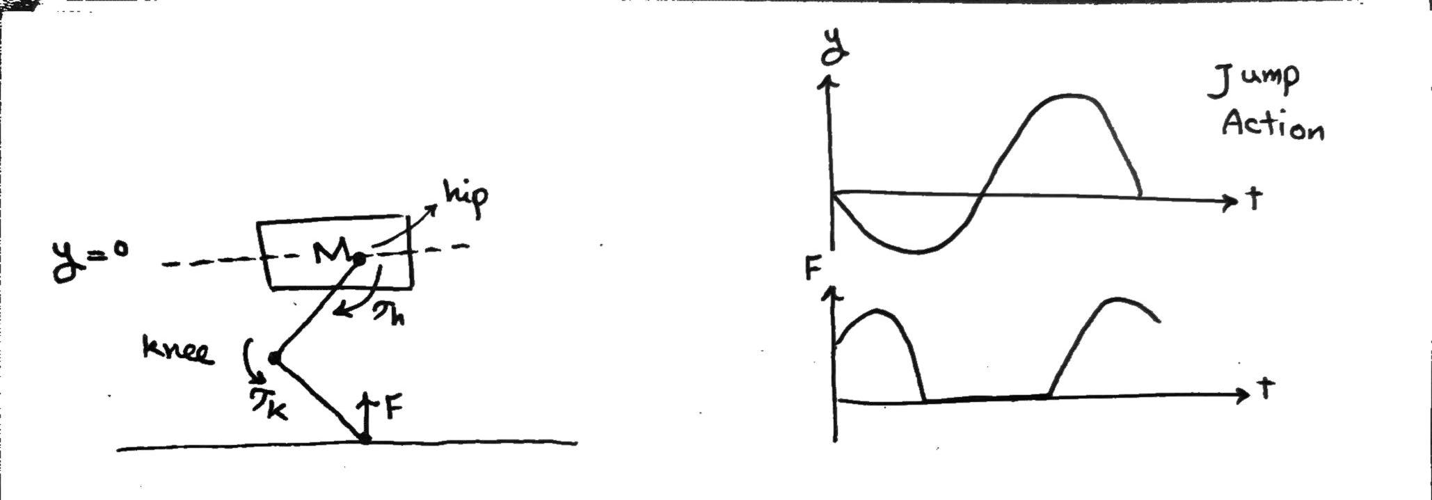 A simple jump action is also demonstrated on the right.
The control goal is to determine appropriate inputs $\tau_h$ and $\tau_k$. such that the $y$ and $F$ follow the desired reference.
A simple jump action is also demonstrated on the right.
The control goal is to determine appropriate inputs $\tau_h$ and $\tau_k$. such that the $y$ and $F$ follow the desired reference.
The dynamic model can be written from two points of view:
- Inertial frame In this frame, the equations take the form of: \([A]\begin{bmatrix} \tau_h \\ \tau_k \end{bmatrix} = \begin{bmatrix} F \\ 0 \end{bmatrix}, [B]\begin{bmatrix} \tau_h \\ \tau_k \end{bmatrix} + [C]\begin{bmatrix} F \\ 0 \end{bmatrix} = \begin{bmatrix} \ddot{y} \\ \ddot{\alpha} \end{bmatrix}\) where $\alpha$ denotes the angle between the mass and the horizonal horizon.
- Body frame In this frame, the equations take the form of: \(M \ddot{q} + C(q, \dot{q}) = \begin{bmatrix} 0 \\ \tau \end{bmatrix} + J^{-1} [F]\) $q$ are the angles of the rods attached to the motors and $J^{-1}$ denotes the inverse dynamics. The direct dynamics $J$ is the mapping from $q$ to Cartesian coordinates $x,y$ . The inverse dynamic is the mapping from the Cartesian coordinates to $q$ values, which is not unique ($J$ might be singular), according to this article. So in this frame, the control inputs are $q$ (there is two of them, one for each motor). $F$ can be seen explicitly in the dynamics, but $y$ is hidden in $J^{-1}$. What is $\tau$ here?
[!note] Note To make designing a controller easier, a typical approximation is used, where it is assumed that $F = ky$. This is called SLIP (Spring-Loaded Inverted Pendulum).
Various authors and robotic teams were suggested, including Alexander Badri-Sprowitz, Marco Hutter in ETH working on Anymal, EPFL and Max Planck teams working on Cheetah Cub, MIT Cheetah and IIT in Italy working on a Hydrolic robot.
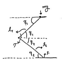
A more clear view of the problem
The angles are defined as below:
 The motors used are brushless DC motors.
In the early days of robotic, stepper motors were used. These motors have control over their angles, so they will go to any angle. The problem with those was that if you exerted enough pressure and force on them, they would turn and lose the right angle. They are also what gave the early robots their signature robot-like movements.
Today, brushless DC motors (BLDC) are used. These motors have a permanent magnet inside a coiling. The voltage applied to the coil is directly related to the motor spinning speed in no load condition. The current applied is directly related to the torque the motor exerts when under load.
The goal in this project is to find the appropriate $V-I$ characteristics (by finding the appropriate $\tau - \dot{q}$ characteristic), so that the right type of motor can be selected.
The motors used are brushless DC motors.
In the early days of robotic, stepper motors were used. These motors have control over their angles, so they will go to any angle. The problem with those was that if you exerted enough pressure and force on them, they would turn and lose the right angle. They are also what gave the early robots their signature robot-like movements.
Today, brushless DC motors (BLDC) are used. These motors have a permanent magnet inside a coiling. The voltage applied to the coil is directly related to the motor spinning speed in no load condition. The current applied is directly related to the torque the motor exerts when under load.
The goal in this project is to find the appropriate $V-I$ characteristics (by finding the appropriate $\tau - \dot{q}$ characteristic), so that the right type of motor can be selected.
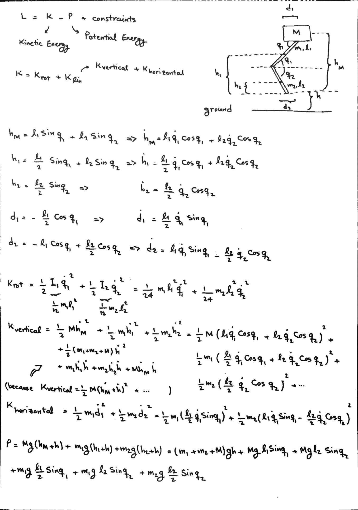
Euler-Lagrange Dynamics
I tried writing the Euler-Lagrange dynamics myself. Here is a sketch of the leg plus the equations:
 a
a
To read more about what’s in the literature, take a look at Robot Leg Equations.